Home » Posts tagged 'backflow testing'
Tag Archives: backflow testing
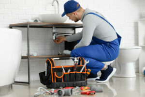
Types of Pipes Used by a Plumber
A plumber is a tradesperson who installs and repairs systems used for potable water, hot-water production, sewage, and drainage in residential and commercial settings. They also collaborate with other professionals, such as construction teams, to ensure plumbing systems are integrated seamlessly into building projects and meet all required standards and regulations. For professional help, contact Plumber Granada Hills.
A test cock is a small valve that allows a plumber to check a backflow preventer assembly for problems such as leaking or stuck valves. This is important because a faulty backflow prevention device can put your water supply at risk of contamination from contaminated sources such as illegal backflow. A plumber who is certified to work on these devices knows when the tests should be done and what types of procedures to follow.
When a backflow prevention device is being tested, the plumber shuts off the downstream water valve and then visually inspects the device and surrounding area for any signs of wear or damage. Then he or she hooks up the test kit hoses to the backflow device using small nozzles built into the preventer called test cocks. These nozzles are usually located near the shut-off valves. They have a slot in the middle through which a flathead screwdriver can be inserted. Then the plumber closes the test cocks by inserting the handle on the screwdriver.
The test cocks on a double-check valve assembly are used to test the operation of both the upstream and downstream shut-off valves, as well as the relief valve. They are also used to measure and analyze pressure data during the test procedure.
In most states, a test-cock must be tamper resistant and must have a non-slip surface. Several different types are available, but the best are those that have a handle that can be locked with a screwdriver or wrench. In addition, the test cocks must be easy to open and close, and they should be clearly marked with numbers.
Some test procedures require the tester to close a number 1 or 2 shut off before performing a direction of flow test on the second check valve. This step is necessary because it prevents the tester from opening the differential pressure relief valve prematurely, which can cause a test failure. But other test procedures do not require this, and some have no requirement for the closing of a shut off valve.
Pressure gauges
Pressure gauges measure pressure and display the readings on a dial or digital readout. They are used in a variety of applications including backflow testing, chemical, automotive, and HVAC. They can be constructed from a wide variety of materials including stainless steel, brass, and plastic. The type of gauge chosen depends on the media it will monitor and the conditions it will be exposed to. Many manufacturers offer a variety of seals for use with different gauge types to protect them from corrosive chemicals and gases as well as from impacts, vibrations, and extreme temperatures.
The functional components of a pressure gauge include a flexible measuring element, a movement mechanism, and a pointer. The measuring element, commonly called a Bourdon tube, is made of elastic material that expands or contracts as the pressure changes. The movement is then converted into a rotary motion that drives the pointer, which indicates the measurement. The pointer is displayed on a dial that can be configured to show either a bar or a scale. The dial diameter varies from 1.5 inches to 16 inches, depending on the location of the gauge and its required accuracy.
Different gauges have various connection types, which are based on the type of installation and environmental factors. Some connections are threaded while others are screwed into place and can be removed without damaging the threads. NPT (National Pipe Taper) and BSPP (British Standard Parallel Pipe) are the most common connection types, but there are also DIN, JIS, and SAE options available.
Diaphragm-type gauges are often preferred for backflow testing since they are more accurate than bellows-type pressure gauges. This is because the diaphragm has high and low pressure applied on opposite sides of it. A stainless steel stem passes through the middle of the diaphragm and is supported on both sides by diaphragm retainers. The gauge case is often liquid-filled, which helps to dampen shocks and vibrations.
It is important to understand the difference between calibration and verification of accuracy. The former is a maintenance function, while the latter is an inspection of a device’s functioning. For example, local administrative authorities may require that a pressure gauge be calibrated annually. However, this does not necessarily mean that the instrument will be verified for accuracy every year.
Gate valves
Gate valves are used in all manner of plumbing systems, both above and below ground. They isolate a section of pipe when necessary and can prevent backflow by opening and closing the flow of liquids. In order to ensure that they perform properly, backflow testing is required on a regular basis. These tests will determine if there are any problems with your backflow system and prevent contaminants from entering the water supply.
The operation of a gate valve is controlled by its trim parts. These include the valve disc or wedge, gland packings, seat rings and the stem. The stem of a gate valve is either a rising or nonrising one. A nonrising stem is almost always equipped with a pointer-type indicator mounted on its upper end to indicate valve position. This design protects the threads from carrying dirt into the valve packing and helps prevent stem damage. Rising stems are used when it is important to know by immediate inspection whether the valve is open or closed. They may be made of a solid or flexible wedge.
A gate valve seat is usually either a slab or a floating type. Slab seats are often cast or welded to the body of the valve while floating seats can be pressed in place and seal welded to the body. These types of seats are best suited for on/off applications where the shearing action of high-velocity flows will cause a partially open valve to chatter and damage its seating surfaces.
Wedge gate valves are guided by grooves or ribs cast or welded into the body of the valve. These guides keep the disk centered as it opens and closes, and they help to prevent the gate from sliding against the downstream seat during the upstream portion of the travel.
Depending on the application, gate valves can be supplied with a range of trim materials, including steel (stellite, 316ss or 347ss), bronze, stainless steel monel and Hastelloy. A flanged or screwed body assembly can also be specified. Some are available with a choice of handwheel actuators, and they can be operated by turning them in one direction to open the valve and in the other to close it.
Relief valves
A relief valve is a safety device that allows excessive pressure to escape the system. It can be used for pump head protection, to vent the contents of a vented tank or to dump water in an emergency. It should be set to a pressure lower than the main pressure setting. This will prevent the operator from adjusting the main relief to an unsafe level. This will eliminate pump or piping damage and protect the operator from injury or death.
It is important to use a valve with a seat leakage test rating. This should be listed on the label and should include corrections for service conditions like backpressure or temperature. The valve should also have a maximum working pressure limit. It is important to test the valves regularly.
If a relief valve is over-pressurized, it may break open and discharge water. A safety relief valve is the only way to prevent this. In addition to preventing backflow, the valves can help maintain a steady line pressure and prevent surges.
The pressure at the point where the valve opens is called its “setpoint”. This is the maximum allowable operating pressure for a given system. This pressure should be measured as pounds per square inch (PSIG) and should be within the pressure-rated limits of the system.
During normal operation, pressure in the system remains low. If a check valve fails, the higher water pressure will go past the leaking check and pressurize the area between the first and second check. This area of reduced pressure is controlled by a diaphragm and is connected to the main relief valve. If the upstream pressure increases to 98.0 PSI or more, then the relief valve will open and pass water.
To avoid this, use a dual check valve circuit that has a relief valve with an external drain. The drain eliminates backpressure at the relief valve vent port so that it can stay open when bypassing. It is also possible to use a single pilot-operated relief valve with 3-position directional control valves to block the vent port on the relief to keep pressure low.